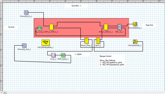
pps 生成代码写入AIC3254没有声音输出
亲爱的TI工程师:
我用PPS生成的代码写入AIC3254只听到杂音,没有声音输入,我用的是CC3200AUDBOOST这块板子做测试,请您帮我看看哪里出了问题。

下面的配置写入预置模式就有声音输入输出,写入PPS生成的minDsp代码就只能听到一点杂音。
reg_value REG_Section_program[] = {
{ 0,0x00},
// # reg[ 0][ 1] = 0x01 ; Initialize the device through software reset
{ 1,0x01},
{ 0,0x00},
// 0x00 16bit, I2S, BCLK is input to the device
{ 27,0x00},
{ 0,0x01},
// # reg[ 1][ 2] = 0xa9 ; Power up AVDD LDO
{ 2,0x01},
// # reg[ 1][ 1] = 0x08 ; Disable weak AVDD to DVDD connection
{ 1,0x08},
// # reg[ 1][ 2] = 0xa1 ; Enable Master Analog Power Control, AVDD LDO Powered
{ 2,0x01},
// # reg[ 1][ 71] = 0x32 ; Set the input power-up time to 3.1ms
{ 71,0x32},
// # reg[ 1][123] = 0x05 ; Force REF charging time to 40ms
{123,0x01},
// miniDSP_D programming mode
{255,0x00},
{255,0x01},
{ 0,0x00},
// # reg[ 0][ 60] = 0x00 ; Use miniDSP_D for signal processing
{ 60,0x00},
// # reg[ 0][ 61] = 0x00 ; Use miniDSP_A for signal processing
{ 61,0x00},
// # reg[ 0][ 17] = 0x08 ; 8x Interpolation
{ 17,0x08},
// # reg[ 0][ 23] = 0x04 ; 4x Decimation
{ 23,0x04},
//
{ 15,0x18},
//
{ 16,0x00},
//
{ 21,0x03},
//
{ 22,0x88},
/*
//miniDSP 预置模式
{ 0,0x00},
{ 60,0x02},
{ 0,0x2c},
{ 1,0x04},
*/
{ 0,0x08},
// # reg[ 8][ 1] = 0x04 ; adaptive mode for ADC
{ 1,0x04},
{ 0,0x00},
// # reg[ 0][ 5] = 0x94 ; // PLL is powered up, P=1, R=4
{ 5,0x94},
// # reg[ 0][ 6] = 0x2A ;J=42
{ 6,0x2A},
// # reg[ 0][ 7] = 0x00 ; D=0000 (MSB)
{ 7,0x00},
// # reg[ 0][ 8] = 0x00 ; D=0000 (LSB)
{ 8,0x00},
// # reg[ 0][ 4] = 0x03 ; PLL Clock is CODEC_CLKIN
{ 4,0x03},
// # reg[ 0][254] = 0x0a ; Delay 10ms for PLL to lock
{254,0x0A},
// # reg[ 0][ 12] = 0x82 ; MDAC = 14, divider powered on
{ 12,0x8E},
// # reg[ 0][ 13] = 0x01 ; DOSR = 384(MSB)
{ 13,0x01},
// # reg[ 0][ 14] = 0x80 ; DOSR = 384(LSB)
{ 14,0x80},
// # reg[ 0][ 18] = 0x82 ; // NADC divider powered up, NADC = 2
{ 18,0x82},
// # reg[ 0][ 19] = 0x95 ; MADC = 21, divider powered on
{ 19,0x95},
// # reg[ 0][ 20] = 0x00 ; AOSR = 256
{ 20,0x00},
// # reg[ 0][ 11] = 0x8E ; NDAC = 2, divider powered on
{ 11,0x82},
//clk output set
{ 25,0x04}, // DAC_CLK
{ 26,0x81},
{ 55,0x06}, // MOSI OUTPUT CLK
{ 0,0x01},
// # reg[ 1][ 51] = 0x40 ; // MICBIAS powered up ON Board Mic
{ 51,0x40},
// # reg[ 1][ 52] = 0x00 ; not routed to Left MICPGA
{ 52,0x00},
// # reg[ 1][ 54] = 0x04 ; IN3R is routed to Left MICPGA with 10k resistance
{ 54,0x04},
// # reg[ 1][ 55] = 0x04 ; IN3R is routed to Right MICPGA with 10k resistance
{ 55,0x54},
// # reg[ 1][ 57] = 0x40 ; CM is routed to Right MICPGA via CM1R with 10k resistance
{ 57,0x40},
// IN3R input is weakly driven to common mode.
{ 58,0x04},
// # reg[ 1][ 59] = 0x5E ; //make channel gain 0dB, since 20K input //impedance is used single ended
{ 59,0x00},
// # reg[ 1][ 60] = 0x00 ; Enable MicPGA_R Gain Control, 0dB
{ 60,0x00},
{ 83,0x68},
{ 84,0x68},
{ 0,0x00},
// # reg[ 0][ 81] = 0xc0 ; Power up LADC/RADC
{ 81,0xC0},
// # reg[ 0][ 82] = 0x00 ; Unmute LADC/RADC
{ 82,0x00},
{ 0,0x01},
// # reg[ 1][ 20] = 0x25 ; De-pop: 5 time constants, 6k resistance
{ 20,0x25},
// # reg[ 1][ 12] = 0x08 ; Route LDAC to HPL
{ 12,0x08},
// # reg[ 1][ 13] = 0x08 ; Route RDAC to HPR
{ 13,0x08},
// # reg[ 1][ 14] = 0x08 ; Route LDAC to LOL
{ 14,0x08},
// # reg[ 1][ 15] = 0x08 ; Route LDAC to LOR
{ 15,0x08},
{ 9,0x3C},
{ 0,0x01},
// # reg[ 1][ 16] = 0x00 ; Unmute HPL driver, 27dB Gain
{ 16,0x1B},
// # reg[ 1][ 17] = 0x00 ; Unmute HPR driver, 27dB Gain
{ 17,0x1B},
// # reg[ 1][ 18] = 0x00 ; Unmute LOL driver, 28dB Gain
{ 18,0x1c},
// # reg[ 1][ 19] = 0x00 ; Unmute LOR driver, 28dB Gain
{ 19,0x1c},
// # reg[ 1][ 20] = 0x25 ; // Headphone ramps power up time is determined with 6k resistance,
{ 0,0x00},
{ 61,0x02},
{ 0,0x00},
// # Digital Volume Control = 64.0dB
{ 65,0x93},
// # Digital Volume Control = 64.0dB
{ 66,0x93},
{ 0,0x00},
// # reg[ 0][ 63] = 0xd4 ; Power up LDAC/RDAC w/ soft stepping
{ 63,0xD6},
{ 64,0x00},
{ 0,0x00},
{ 86,0x20},
// # reg[0][87] = 254
{ 87,0xFE},
// # reg[0][88] = 0
{ 88,0x00},
// # reg[0][89] = 104
{ 89,0x68},
// # reg[0][90] = 168
{ 90,0xA8},
// # reg[0][91] = 6
{ 91,0x06},
// # reg[0][92] = 0
{ 92,0x00},
};
没有声音输入, 对于高输入阻抗的电路, 如果悬空的输入会感应到很多噪声, 不知道你是否也是遇到的这个问题
的确会引入噪音,硬件噪音的话难免的吧,MinDsp 可以软件上可以做噪音消除,就是用PPS生成的代码我还没调试成功过,现在只调试成功了预置模式的功能。您能否指教一下我上面的代码有啥问题。谢谢!
