ADS1299内部测试信号数据问题
时间:10-02
整理:3721RD
点击:
之前买了ADS1299的评估板,我利用MCU(cc2530)板子对ADS1299套件子板供电并实现spi连接,已经成功读出ID。
再进行内部信号测试的时候出现方波不稳(个别点跳跃)的情况(评估板测试方波良好),我检查了一下得到的原始数据发现个别位置出现数据错误(图中蓝线所示部分),请问这是什么原因?应该如何改正呢?
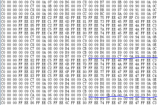
好象没有明确规则的数据发生错误.
不过我感觉不见得是芯片的采集问题, 也可能软件有缺陷. 数据应该有的, 发生了放置的错位
感谢你的回复!
感觉应该是我读取数据的问题,以下是我配置管脚、寄存器、读取数据的代码,能请您帮我查看一下吗?
#define SPI_DRDY      P1_2
#define CLKSEL        P1_3
#define SPI_START     P0_6
#define PWDN         P0_5
#define RESET        P0_4
int spi_init()
{
    // SPI Master Mode
    PERCFG |= 0x02;        // map USART1 to its alternative 2 location. P1_4: SSN, P1_5: SCK, P1_6: MOSI, P1_7: MISO
    P1SEL |= 0xE0;        // P1_5, P1_6, and P1_7 are peripherals
    P1SEL &= ~0x10;        // P1_4 is GPIO (SSN)
    P1DIR |= 0x10;        // SSN is set as output

    U1BAUD = 0x00; U1GCR |= 0x0D;        // BAUD_M=0,BAUD_E=13,Fsck=250kHz.4us
    U1CSR &= ~0xA0;        // SPI Master Mode
    //        U1CSR &= ~0x80; U1CSR |= 0x20;        // SPI Slave Mode
    //U1GCR &= ~0xC0; U1GCR |= 0x20;        // MSB
    U1GCR = 0x6D;

    //IO_FUNC_PORT_PIN(1, 4, IO_FUNC_GIO);
    IO_FUNC_PORT_PIN(1, 2, IO_FUNC_GIO);
    IO_DIR_PORT_PIN(1, 2, IO_IN);
    IO_FUNC_PORT_PIN(1, 3, IO_FUNC_GIO);
    IO_DIR_PORT_PIN(1, 3, IO_IN);
    IO_FUNC_PORT_PIN(0, 6, IO_FUNC_GIO);
    IO_DIR_PORT_PIN(0, 6, IO_IN);

    IO_DIR_PORT_PIN(1, 4, IO_OUT);
    IO_DIR_PORT_PIN(1, 5, IO_IN);
    IO_DIR_PORT_PIN(1, 6, IO_OUT);
    IO_DIR_PORT_PIN(1, 7, IO_IN);

    IO_FUNC_PORT_PIN(1, 1, IO_FUNC_GIO);    //
    IO_DIR_PORT_PIN(1, 1, IO_OUT);          //
    IO_FUNC_PORT_PIN(1, 0, IO_FUNC_GIO);
    IO_DIR_PORT_PIN(1, 0, IO_OUT);
    return 0;
}
void main()
{
    char  temp[3];
    unsigned char  out[27];
    uint32 uartout[200];
    CLKCONCMD = 0x80; while (CLKCONSTA != 0x80);        // 32MHz
    InitUart();
    spi_init();
    LED1 = 1;

    P1_3 = 1;               //CLKSET = 1
    halMcuWaitUs(1000);
    P0_5 = 1;               //PWDN = 1

    P0_4 = 1;               //RESET pin =1

    //while(1){
    P1_4 = 0;               //SSN = 0;
    halMcuWaitUs(16);
    WriteData(0x06);        //RESET
    halMcuWaitUs(36);
    P1_4 = 1;
    halMcuWaitUs(16);
    P1_4 = 0;
    halMcuWaitUs(16);
    WriteData(0x11);       //SDATAC
    halMcuWaitUs(16);
    P1_4 = 1;
    halMcuWaitUs(16);

    P1_4 = 0;
    halMcuWaitUs(16);
    WriteData(0x43);       //WREG and from 0x03h address
    halMcuWaitUs(32);
    WriteData(0x00);       //only CONFOG3
    halMcuWaitUs(32);
    WriteData(0xE0);
    halMcuWaitUs(32);
    P1_4 = 1;
    halMcuWaitUs(16);

    P1_4 = 0;
    halMcuWaitUs(16);
    WriteData(0x42);       //WREG and from 0x02h address
    halMcuWaitUs(32);
    WriteData(0x00);       //only CONFOG2
    halMcuWaitUs(32);
    WriteData(0xD0);
    halMcuWaitUs(32);
    P1_4 = 1;
    halMcuWaitUs(16);

    P1_4 = 0;
    halMcuWaitUs(16);
    WriteData(0x45);       //WREG and from 0x05h address
    halMcuWaitUs(32);
    WriteData(0x07);       //eight channels | CHnSET
    halMcuWaitUs(32);
    WriteData(0x05);
    halMcuWaitUs(32);
    WriteData(0x05);
    halMcuWaitUs(32);
    WriteData(0x05);
    halMcuWaitUs(32);
    WriteData(0x05);
    halMcuWaitUs(32);
    WriteData(0x05);
    halMcuWaitUs(32);
    WriteData(0x05);
    halMcuWaitUs(32);
    WriteData(0x05);
    halMcuWaitUs(32);
    WriteData(0x05);
    halMcuWaitUs(32);
    P1_4 = 1;
    halMcuWaitUs(16);
    //P0_6 = 1;              //START=1
    //halMcuWaitUs(4);

    P1_4 = 0;
    halMcuWaitUs(16);
    WriteData(0x10);       //Come back to RDATAC Mode
    //halMcuWaitUs(16);
    P1_4 = 1;
    P0_6 = 1;              //START=1
    while(1)
    {
      if(P1_2 == 0){
        for(int i=0;i<27;i++){
          //for(int j=0;i<3;j++){
            P1_4 = 0;
            U1DBUF = 0x00;
            while(!U1TX_BYTE);
            //temp[j] = U1DBUF;
            out[i] = U1DBUF;
            P1_4 = 1;
            U1TX_BYTE = 0;
          //}
          //out[i] = temp[0]+temp[1]+temp[2];
          //uartout[i]=hexStr2Str(out);

          //sprintf(uartout[i],"%6X",out);
        }
       //out[27] = 0xFF;
       UartSendString(out,27);
       halMcuWaitMs(100);
      }
    }


}
你的ADS1299的ID在初始化的时候设置的是多少啊?