请问谁能提供下ADS8638或者ADS8634的verilog的控制程序吗?
目前在调试ADS8638这块芯片,但是发现配置的数据都没有什么用。芯片的输出都没有什么反应。
麻烦各位大神给小弟看看这段代码的逻辑和时序以及配置的数据 问题在哪里!
谢谢了!
/**********************************************************************************/
// Module Name : ADC8638_Crtl.v
// Invoker :
// Company :
// Dept :
// Function : ADS8638 Control
// Description :
// Revision : 1.0
// Date : 2016.03.25
// History :
/**********************************************************************************/
module ADC8638_Ctrl(clk_i, // Serial Clk input
rst_n_i, // reset signal
updt_data_i, // ADC data input
adc_sclk_o, // adc clock output to ads8638
adc_data_o, // adc serial data output to dsp
adc_cs_o, // adc cs signal output to ads8638
adc_din_o, // adc control signal output to ads8638
adc_al_pd_o // adc al_pd signal output to ads8638
);
input clk_i; // serial clock input
input rst_n_i; // reset signal input
input updt_data_i; // adc data input
output adc_sclk_o; // adc clock output to ads8638
output adc_cs_o; // adc cs signal output to ads8638
output adc_din_o; // adc control signal output to ads8638
output adc_al_pd_o; // adc al_pd signal output to ads8638
output [15:0]adc_data_o; // adc serial data output to dsp
/**********data from ads8638**********/
reg updt_data_i_q,updt_data_i_qq,updt_data_i_qqq;
always @ (posedge clk_i)
begin
updt_data_i_q <= updt_data_i;
updt_data_i_qq <= updt_data_i_q;
updt_data_i_qqq <= updt_data_i_qq;
end
/**********sclk to ads8638**********/
reg adc_sclk_o;
always @ (posedge clk_i)
begin
adc_sclk_o<=adc_sclk_o+1; // adc_clk = clk_i / 2
end
/**********state machine**********/
parameter [3:0]
IDLE = 4'b 0000,
Confg_Aux = 4'b 0001,
Confg_delay1 = 4'b 0011,
Confg_ChSel = 4'b 0010,
Confg_delay2 = 4'b 0110,
Confg_Auto = 4'b 0100,
Wait = 4'b 0101,
Start = 4'b 0111,
Read = 4'b 1111;
reg [3:0]state;
reg [2:0]config_cnt;
reg [5:0]counter;
always @ (posedge clk_i)
begin
if(!rst_n_i)
begin
state <= IDLE;
config_cnt = 3'b 0;
end
else if (~adc_sclk_o)
begin
case(state)
/***********************************************************/
IDLE:
begin
state <= Confg_Aux;
end
/***********************************************************/
Confg_Aux: //config auxiliary control register
begin
state <= Confg_delay1;
end
/***********************************************************/
Confg_delay1:
begin
if(counter==6'b 01_0000) //finish first config and delay
begin
state<=Confg_ChSel;
end
else
state<=Confg_delay1;
end
/***********************************************************/
Confg_ChSel: //config channel selection register
begin
state <= Confg_delay2;
end
/***********************************************************/
Confg_delay2:
begin
if(counter==6'b 01_0000) // finish second config and delay
begin
state<=Confg_Auto;
end
else
state<=Confg_delay2;
end
/***********************************************************/
Confg_Auto: //config auto-scan mode register
begin
state <= Wait;
end
/***********************************************************/
Wait: //interim state ,pull cs signal high
begin
if(counter==6'b 01_0000)
begin
if(config_cnt==3'b 010) // write config register 4 times
begin
state <= Start;
end
else
begin
config_cnt <= config_cnt + 1'b1;
state <= IDLE;
end
end
else
state <= Wait;
end
/***********************************************************/ //Read digital data,16bit
Start:
begin
state <= Read;
end
/***********************************************************/
Read:
begin
if(counter==6'b 01_0000) //device output the AD data while convertion
state <= Start;
else
state <= Read;
end
/***********************************************************/
default:state <= IDLE;
endcase
end
end
/*************************counter**********************************/
always @ (posedge clk_i)
begin
if((state==Confg_Aux)||(state==Confg_ChSel)||(state==Confg_Auto)||(state==Start))
counter <= 6'b00_0000;
else if((counter!=6'b 01_0000)&(~adc_sclk_o))
counter <= counter +1'b 1;
else
counter <= counter;
end
/*************************CS signal**********************************/
reg adc_cs_o;
always @ (posedge clk_i)
begin
if((counter==6'b00_0000)&(~adc_sclk_o))
//if((state==Confg_Aux)||(state==Confg_ChSel)||(state==Confg_Auto)||(state==Start))
adc_cs_o <= 1'b 1;
else if((state==IDLE)&(~adc_sclk_o))
adc_cs_o <= 1'b 1;
//else if(counter==6'b 00_0001)
else if((counter==6'b 00_0001)&(~adc_sclk_o))
adc_cs_o <= 1'b 0;
/*************************
else if((state==Confg_delay1)&(counter==6'b 00_1111)&(~adc_sclk_o))
adc_cs_o <= 1'b 1;
else if((state==Confg_delay2)&(counter==6'b 00_1111)&(~adc_sclk_o))
adc_cs_o <= 1'b 1;
else if((state==Wait)&(counter==6'b 00_1111)&(~adc_sclk_o))
adc_cs_o <= 1'b 1;
else if((state==Read)&(counter==6'b 00_1111)&(~adc_sclk_o))
adc_cs_o <= 1'b 1;
**********************************/
else
adc_cs_o <= adc_cs_o;
end
//assign adc_cs_o = 1'b1;
/**********shift out data to ads8638***********/
reg [15:0]shift_out_reg;
always @ (posedge clk_i)
begin
if(state==Confg_Aux)
//shift_out_reg<=16'b 0000_0000_0000_0000;
shift_out_reg<=16'b 0000_110_0_0000_1100; // 06h,write to config register,al_pd power down mode,Int Vref enable,temp sensor unable
else if(state==Confg_ChSel)
//shift_out_reg<=16'b 0000_0000_0000_0000;
shift_out_reg<=16'b 0001_100_0_1111_1111; // 0Ch,write to channel selection register,all channels be selected
else if(state==Confg_Auto)
//shift_out_reg<=16'b 0000_0000_0000_0000;
shift_out_reg<=16'b 0000_101_0_0000_0010; // 05h,write to auto-scan mode register,all channel ±10V input
else if(state==Start)
//if(state==Start)
shift_out_reg<=16'b 0000_0000_0000_0000; // 00h,hold DIN low to continue the device operation in the last selected mode
else if((~adc_cs_o)&(~adc_sclk_o))
shift_out_reg<={shift_out_reg[14:0],1'b0}; // shift out to adc
else
shift_out_reg<=shift_out_reg;
end
assign adc_din_o = shift_out_reg[15]; // adc serial data output to ads8638
assign adc_al_pd_o = 1'b 1;
/**********shift in data from ads8638***********/
reg [15:0] shift_in_reg;
always @ (posedge clk_i or negedge rst_n_i)
begin
if(!rst_n_i)
shift_in_reg <= 15'b 0;
// else if((state==Start) & (~adc_sclk_o))
else if(state==Read)
shift_in_reg <= {shift_in_reg[14:0], updt_data_i_qqq};
end
/********* Read ADC Data **************************/
reg [15:0]adc_data_o;
always @ (posedge clk_i or negedge rst_n_i)
begin
if(!rst_n_i)
begin
adc_data_o <= 16'b 1111_1111_1111_1111;
end
else begin
if(state == Start)
adc_data_o <= shift_in_reg[15:0];
else
adc_data_o <= adc_data_o;
end
end
//assign adc_data_o = shift_in_reg[15:0];
endmodule
找了一下,应该没有。
可以帮我分析下上面的代码吗?
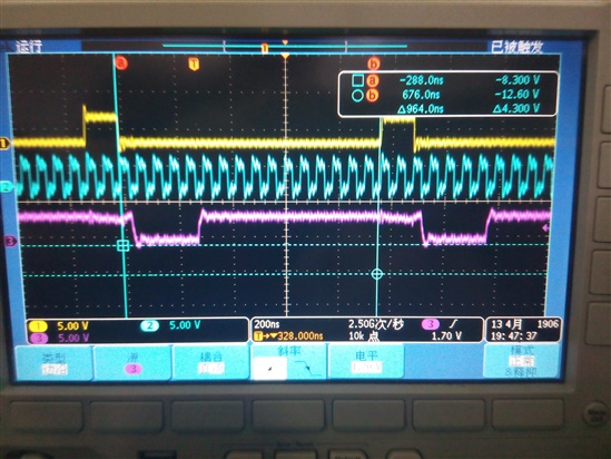
这张波形 对应的是配置第一个aux寄存的数据,0000_1100_0000_1100,
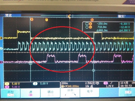
这是配置channel selection 寄存器的数据,0001_1000_1111_1111
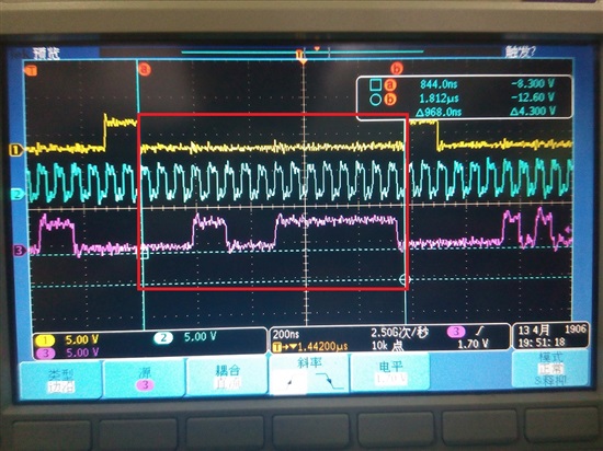
这是配置成auto scan的数据,0000_1010_0000_0010
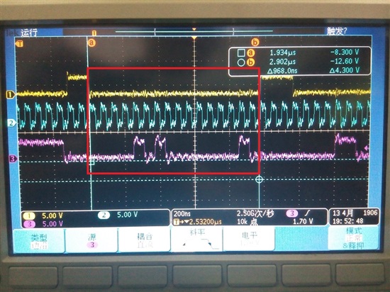
波形跟我要发送的数据都应该是正常的,但是配置好之后,ADC输出的数据却不会改变