ads1204 基于fpga的sinc3滤波
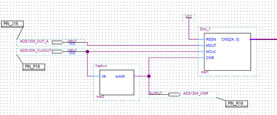
上图是我用vhdl语言在quartus 软件内绘制的针对ads1204的输出数据滤波模块,图中ADS1204_OUT_A 代表芯片的数据输出口,ADS1204_CLKOUT 代表芯片输出时钟,fredivn表示256分频即起到OSR=256的作用,sinc_1表示sinc3滤波。请问设计思路是否正确?我测试的结果是经过滤波后输出数据变化非常大,不知道问题出在哪里,请指教!
附件vhdl代码:
【fredivn】
library ieee;
use ieee.std_logic_1164.all;
use ieee.std_logic_arith.all;
use ieee.std_logic_unsigned.all;
entity fredivn is
port (clk:in std_logic;
outclk:out std_logic);
end fredivn;
architecture rtl of fredivn is
signal count:integer:=0;
begin
process(clk)
begin
if(clk'event and clk='1') then
if(count=255)then
count<=0;
else
count<=count+1;
if count<128 then
outclk<='0';
else
outclk<='1';
end if;
end if;
end if;
end process;
end rtl;
【sinc3】
library IEEE;
use IEEE.std_logic_1164.all;
use IEEE.std_logic_unsigned.all;
entity Sinc_1 is
port(RESN, MOUT, MCLK, CNR : in std_logic;
CN5 : out std_logic_vector(24 downto 0));
end Sinc_1;
architecture RTL of Sinc_1 is
signal Z1 : std_logic_vector(24 downto 0);
signal Z2 : std_logic_vector(24 downto 0);
signal Z3 : std_logic_vector(24 downto 0);
signal Z4 : std_logic_vector(24 downto 0);
signal Z5 : std_logic_vector(24 downto 0);
signal Z6 : std_logic_vector(24 downto 0);
signal Z7 : std_logic_vector(24 downto 0);
begin
process(MCLK, RESN)
begin
if RESN = '0' then
Z1 <= (others => '0');
Z2 <= (others => '0');
Z3 <= (others => '0');
elsif MCLK'event and MCLK = '1' then
Z1 <= Z1 + MOUT;
Z2 <= Z2 + Z1;
Z3 <= Z3 + Z2;
end if;
end process;
process(CNR, RESN)
begin
if RESN = '0' then
Z4 <= (others => '0');
Z5 <= (others => '0');
Z6 <= (others => '0');
Z7 <= (others => '0');
elsif CNR'event and CNR = '1' then
Z4 <= Z3;
Z5 <= Z3 - Z4;
Z6 <= Z3 - Z4 - Z5;
Z7 <= Z3 - Z4 - Z5 - Z6;
end if;
end process;
CN5<= Z7;
end RTL;
您好,
SINC3滤波器中 OSR并非 是通过对时钟分频来实现的!
在以下应用笔记中有 DS调制器和数字滤波器的原理介绍 以及 SINC3滤波器的VHDL实现示例,你可以参考一下:
http://www.ti.com/general/docs/lit/getliterature.tsp?baseLiteratureNumber=sbaa094&fileType=pdf
我记得你在上一个贴中提及 " 我采用的是sinc3滤波,就是TI提供的vhdl 代码在fpga内实现。"请问你参考是哪里的代码?
为了让问题讨论地更为系统和深入,敬请尽量将尚无答案的相关问题集中在一个贴里面!谢谢支持!
Br
Martin
1.我参考的vhdl代码是:TI 官网上的 check for samples :AMC1204 AMC1204B ------“20MHz, Second-Order, Isolated Delta-Sigma Modulator for Current-Shunt Measurement” 第20页。
2.谢谢指导。
OSR 既然不同过分频来实现,那该如何实现呢!
你给的链接我已拜读,但是不明白该如何设计fpga的总体结构
http://wenku.baidu.com/view/ff60a8f24693daef5ef73dce.html
这个链接应该可以很好地帮助您设计fpga的总体结构
SINC3滤波器中 OSR并非 是通过对时钟分频来实现的!
设计思路应该是没有问题的。
测试的结果是经过滤波后输出数据变化非常大,这句话是什么意思,能不能贴上具体点的图片或者数值呢?
假如0V的模拟电压经过delta-sigma调制器后,再经过sinc3滤波,滤波器输出的结果是一个固定不变的数字还是一直变化的数字?
hit ironman
假如0V的模拟电压经过delta-sigma调制器后,再经过sinc3滤波,滤波器输出的结果是一个固定不变的数字还是一直变化的数字?
理论上应该是一个固定不变的数字的。
你好,请问您的问题解决了吗?我也遇到了相同的问题。
我这里测试的程序 也是这样的,不知道为什么?
Mout不像手册里面描述的,是一个占空比信号!