关于LMH7322VCCO引脚的输入输出问题
在准备比赛的过程中,尝试用LMH7322作为比较器输出方波,然后按照数据手册选取了1.0和1.4的输出配置,采用+-5供电,2.5(AMS117_2.5)给VCCO.
实际测试的时候发现,VCCO输出一个4V的电压,甚至把我的AMS117的输出上拉至4V。QA的输出是以2.7上下摆幅200mv的方波
然后,我将VS改为+-2.5的时候,VCCO依旧用2.5输入,这下QA才正常输出了1.2V上下摆幅200MV的方波,
是datasheet出错了,还是我的这个配置有问题。
讲道理这么几个配置引脚应该不会出错啊。
跪求工作人员或者高手帮忙解决
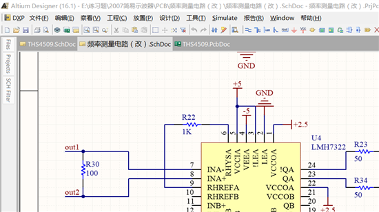
问题应该出在LE和LE-not的连接上,注意LE参考的是VCCO,而不是VS。datasheet中有介绍,当VCCO和VS不同时,特别需要注意LE:
If the LE pin is connected to VEE via a resistor of 10 kΩ and the LE-not pin is connected via 10 kΩ to the VCCO pin the part is continuously on. Since the latch input stage is referenced to VCCO, the resistors to set the LE function should be connected to this voltage. This is very important when working with different voltages for VCCI and VCCO. If connected to the wrong supply, the latch function will not work.
谢谢您,Tina仿真的时候LE接地,LE-not串5K到5V是输出1.2的,我就直接采用了,忽略了LE,