TI-NA信号编辑器请教
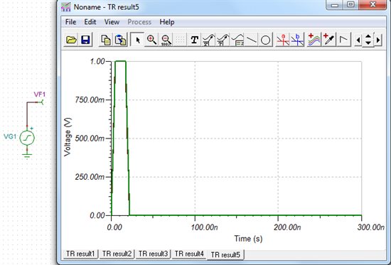
大家好,请问如何在TI-NA里的信号编辑器中生成自己的激励波形,比如:产生上升沿5ns、下降沿5ns、脉冲宽度12ns的单脉冲激励信号!
没用过,不过您可以看看Help文档。。。
Signal Editor
Standard excitations
Once you have selected a Voltage or Current Generator, you can use the Signal Editor to specify the generator waveform. Move the cursor to the signal window, click once and see the ... button appear, then click on the ... button and the Signal Editor becomes available.
All signal waveform functions are defined for t > 0 and start at t = + 0 except for the unit step and general waveform, where you can set the starting point. However, the DC level is already active before the starting time. This feature can be used to enter initial values from a previous DC analysis.
A variety of signal waveforms are available, including Pulse, Unit step, Sinusoidal, Cosinusoidal, Square, Triangle, General, Piecewise linear, User-defined and Wave. All waveforms have several parameters which become available after you have chosen the waveform.
The Pulse waveform has parameters for amplitude and width.
The Unit step waveform has parameters for amplitude and time.
For Sinusoidal and Cosinusoidal waveforms, you may enter the 0-peak amplitude, phase, and the frequency.
For the Square waveform, you may enter the 0-peak amplitude, frequency, and rise/fall time.
For the Triangle waveform, you may enter the 0-peak amplitude and the frequency.
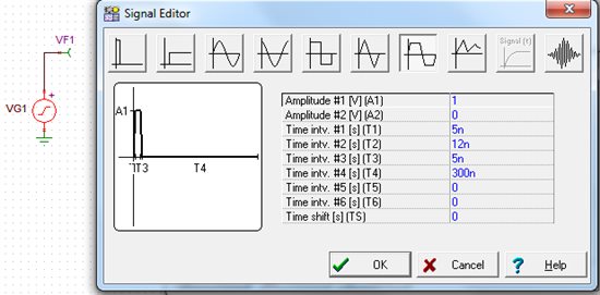
The General waveform permits waveform definition over 6 intervals and two levels, with a time shift parameter as well.
When you select the Piecewise linear waveform you must specify the time-voltage/current pairs which describes the corner of the waveform. The values must be entered according to the PSpice syntax. Time and value scale factors can be used.
User defined excitation
Another important feature of the interpreter is the ability to create user defined signals. This allows you to examine the response of the circuit to any kind of excitation. The User defined waveform is extremely general and provides an equation editor window where the waveform may be defined as a mathematical expression.
To create a user-defined excitation, insert a voltage or current generator in the circuit and set the signal parameter of the generator to user defined. When the signal editor appears, you can create the signal. The structure of the user defined signal is as follows. There must be a special function called Signal, with only one formal parameter. This function will be evaluated during the simulation. There can be other function definitions as well, and the functions can call each other.
You can save the function definition itself for later use in a .EXC file. You can also load previously stored excitations. The stored signals can also be loaded to several generators.
The menu structure of the signal editor is similar to the interpreter's main menu except for the last menu line. This command compiles the signal definition and quits the editor. You can leave the editor in the usual way as well.
When you have finished entering your function, click on the Test button. If the function is syntactically OK, the program will draw the function and you will receive the message Successfully compiled.
A separate window appears below the equation editor. It contains a list of the symbols for pre-defined variables, circuit variables, and other User defined functions. You may use these in creating a User defined waveform.
When signal definition is complete, press the OK button and return to the top level menu window, where clicking on OK returns you to the schematic editor.
Example:
You can define an exponential signal in the following way:
Function Signal(t);
Begin
Signal := 1-exp(-t/1e-6);
End;
Options
You can modify the parameters used to preview user-defined signals.
Drawing parameters:
interval subdivisions -- The number of subdivisions (i.e., calculation
points) used in drawing the preview. The default value is 100.
t_max -- The end time of the preview drawing. The default value is 20us.
These parameters do not affect the time control of the Transient or other analyses.
Periodic: No/Yes. If Yes (press the yes Radio button), the excitation defined in the time interval
0 - t_max will be periodically repeated.
Note: You can also define excitations by tables (list of values) using the Spice PWL function.
For more information check the PWL.TSC circuit in the TINA's EXAMPLES folder.
Wave excitation
In this mode the output of the generator is defined by a content of a wave file. The wave file can be either mono or stereo. In case of a stereo file you have to set the left/right channel. The waveform can be repeated continuously if you check the Repeat option. A media player control is presented for previewing the wave file.
step1:
step2: