基于FPGA的ADS7822模数转换芯片控制程序设计
时间:10-02
整理:3721RD
点击:
这个程序是想通过fpga来控制ADS7822,ADS7822时序图如下

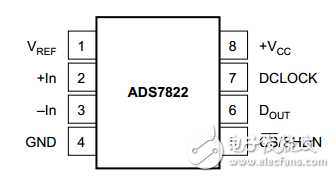
引脚图

程序的时序仿真图如下:
由于图太大没法全部截下来,先是输入

输出却是这样的

想请教各位大神,我的程序哪里出问题了,还是仿真波形没有设置好呢?已经困扰好几天了,跪求解答!源程序如下
library ieee;
use ieee.std_logic_1164.all;
entity adc is
port(clk:std_logic;--时钟
key:std_logic_vector(3 downto 0);--按键输入,“0111”时开始转换,”1011“时停止转换
cs:out std_logic;
D_in:in std_logic_vector(15 downto 0);--数据输入
D_out:out std_logic_vector(15 downto 0));--数据输出
end adc;
architecture rt1 of adc is
signal keyon:std_logic:='0';
begin
process(clk)
variable count:integer range 0 to 15;--数据输入计数,16位时置0
variable x:integer range 0 to 2;
variable state:integer range 0 to 2;--状态变量,0状态是转换刚开始,但须2个时钟周期来进行采样;
begin --1状态是数据传输,传送12位数据;2时截止状态
if(key="0111")then
keyon cs if(count cs cs if(count cs<='1';state:=0;
end case;
--end if;
else cs<='1';
end if;
end if;
end process;
end rt1;

引脚图

程序的时序仿真图如下:
由于图太大没法全部截下来,先是输入

输出却是这样的

想请教各位大神,我的程序哪里出问题了,还是仿真波形没有设置好呢?已经困扰好几天了,跪求解答!源程序如下
library ieee;
use ieee.std_logic_1164.all;
entity adc is
port(clk:std_logic;--时钟
key:std_logic_vector(3 downto 0);--按键输入,“0111”时开始转换,”1011“时停止转换
cs:out std_logic;
D_in:in std_logic_vector(15 downto 0);--数据输入
D_out:out std_logic_vector(15 downto 0));--数据输出
end adc;
architecture rt1 of adc is
signal keyon:std_logic:='0';
begin
process(clk)
variable count:integer range 0 to 15;--数据输入计数,16位时置0
variable x:integer range 0 to 2;
variable state:integer range 0 to 2;--状态变量,0状态是转换刚开始,但须2个时钟周期来进行采样;
begin --1状态是数据传输,传送12位数据;2时截止状态
if(key="0111")then
keyon cs if(count cs cs if(count cs<='1';state:=0;
end case;
--end if;
else cs<='1';
end if;
end if;
end process;
end rt1;
建议 在仿真时添加中间变量的仿真波形 key_on,x ,state, count等 查看是否触发 执行条件
