使用ADS內建的PLL模組,並且運用在IQ modulation之問題
时间:10-02
整理:3721RD
点击:
請問各位高手們
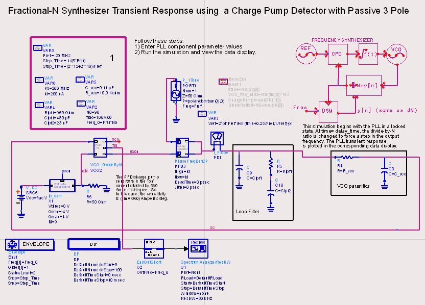
當使用ADS內建的PLL時,該如何實際量測到Fout=OCS*N的輸出頻率呢?
我目前遇到的狀況如下:
VCO_DivideByN這顆元件的freq接腳拉出一條線連接到Specturn,然後在搭配DF與Envelope這兩個模擬元件,並且試著想直接量測到輸出頻率,但問題來了跑出來的結果訊息如下:
Error detected by hpeesofsim during Ptolemy Simulation initialization 'DF'.
output#1 of Cosim '_2_' : Has been resolved to have a timed data type. but the time step has been resolved to 0. At least one device in the graph must set the time step.
我嘗試著去修正,但結果並未改善,在這邊想請問各位高手們可否教教我呢?拜託!
PLL
幫幫我阿!
請問,我要怎麼開啟Spectrum simulation呢?
VCO2.CMP63 , (1 x freq[1]) = 2e+07 Hz is 2e+07 Hz away from the closest analysis frequency at 0 Hz.
The maximum allowed frequency difference is 1.536e+07 Hz.
The spectral component is turned off for this simulation.
In FDD instance VCO2.CMP63 , (1 x freq[2]) = 2e+07 Hz is 2e+07 Hz away from the closest analysis frequency at 0 Hz.
The maximum allowed frequency difference is 1.536e+07 Hz.
This term is ignored and set to 0 for this simulation.